
Skip to content
Agitator assembly & impeller design

Agitation engineered for the duty.

Agitator assemblies and impellers are a Steelcon speciality in their own right — designed from the process duty, built in the alloys our reactors are made of, and trial-run on our own benches before they leave Ankleshwar. We supply them with new vessels, as stand-alone assemblies, or as upgrades to equipment already in service.

Discuss your mixing duty What to tell us
150 HP
Largest agitator drive; several 75 HP assemblies also supplied
90 kL
Largest agitated equipment — a reactor
20 kL
Reactor agitator systems — 10, 12, 15 and 20 kL
60 kL
Agitated storage tank

Figures are references from equipment already supplied, not limits — larger drives, vessels and special configurations are engineered to suit each project.

Illustration, not to scale

Anatomy of an assembly

Every part chosen for the duty.

A top-entry agitator on a jacketed, baffled vessel, part by part. Side- and bottom-entry, centre-line or offset, and multi-stage shafts follow the same logic.

Scroll to open it up.

Drive01 / 05

1Motor
FLP or non-FLP, flange- or foot-mounted.
2Gearbox
Inline, parallel or right-angle.

Mounting and seal02 / 05

3Bearing housing & coupling
Matched to the vessel, the seal and the site conditions.
4Shaft seal
Single or double mechanical seal, stuffing box or sealless magnetic-drive coupling.
5Entry & mounting
Top, side or bottom entry; centre-line or offset.

Shaft and impellers03 / 05

6Shaft
Checked for critical speed, deflection and bending; single or multi-stage.
7Impellers
Type, diameter, speed and power selected for blending, solids suspension, gas dispersion, heat transfer or high-shear dispersion.

Vessel and flow04 / 05

8Baffles
Baffled or unbaffled vessels, to suit the flow pattern.
9External jacket
Conventional jacket to ASME Section VIII, over 65 to 80% of the shell and the bottom head.

The whole assembly05 / 05

Designed from the process duty.

Agitator assemblies and impellers are built in the alloys our reactors are made of, and trial-run on our own benches before they leave Ankleshwar.
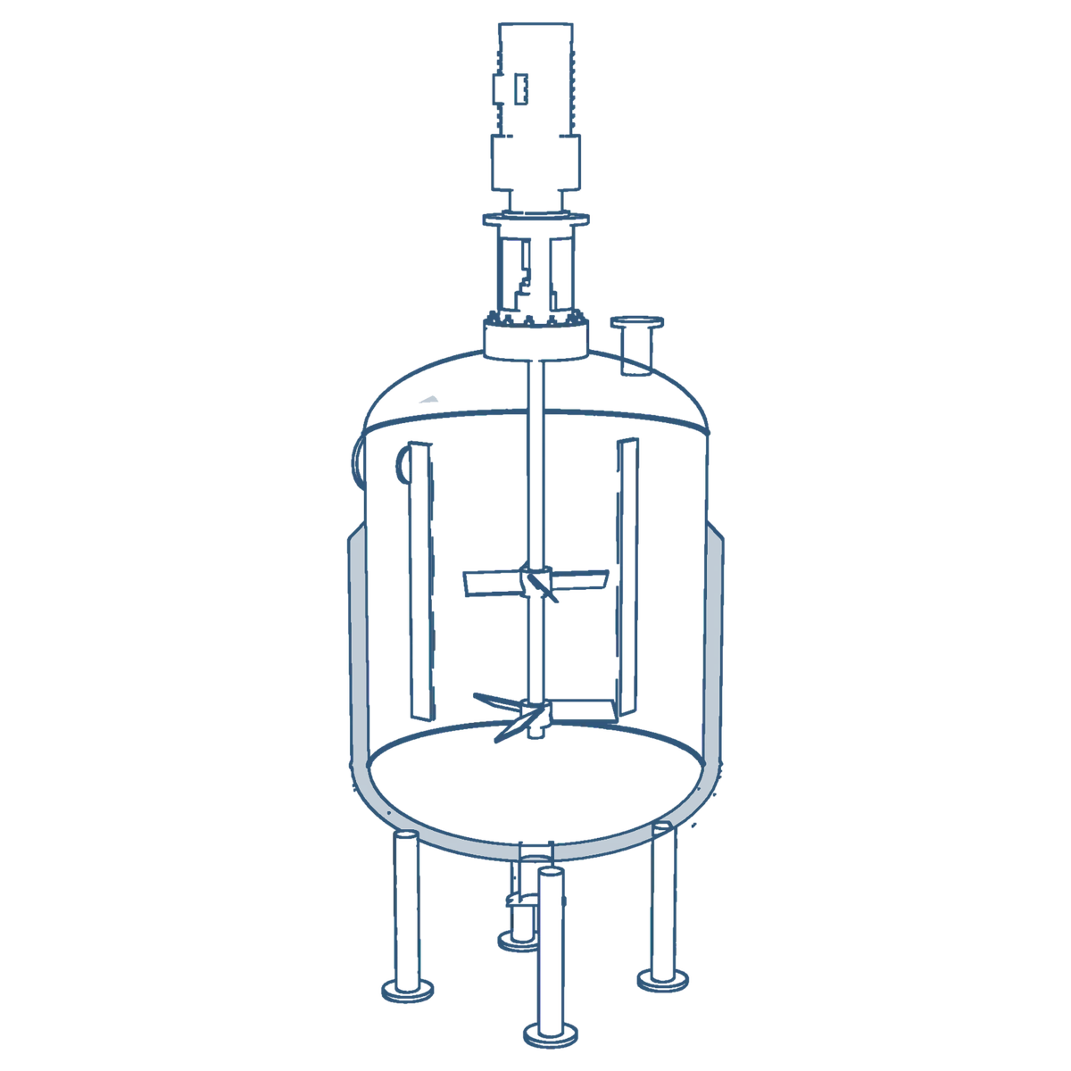
Cut-away drawing of a top-entry agitator on a jacketed, baffled vessel. Numbered parts: 1 motor, 2 gearbox, 3 bearing housing and coupling, 4 shaft seal, 5 entry and mounting flange, 6 shaft, 7 impellers, 8 baffles, 9 external jacket.
Illustration, not to scale
Anatomy of an assembly

Every part chosen for the duty.

A top-entry agitator on a jacketed, baffled vessel, part by part. Side- and bottom-entry, centre-line or offset, and multi-stage shafts follow the same logic.

  1. 1MotorFLP or non-FLP, flange- or foot-mounted.
  2. 2GearboxInline, parallel or right-angle.
  3. 3Bearing housing & couplingMatched to the vessel, the seal and the site conditions.
  4. 4Shaft sealSingle or double mechanical seal, stuffing box or sealless magnetic-drive coupling.
  5. 5Entry & mountingTop, side or bottom entry; centre-line or offset.
  6. 6ShaftChecked for critical speed, deflection and bending; single or multi-stage.
  7. 7ImpellersType, diameter, speed and power selected for blending, solids suspension, gas dispersion, heat transfer or high-shear dispersion.
  8. 8BafflesBaffled or unbaffled vessels, to suit the flow pattern.
  9. 9External jacketConventional jacket to ASME Section VIII, over 65 to 80% of the shell and the bottom head.

What we design and build

01

Process-duty sizing

Impeller type, diameter, speed and power selected for the job it has to do — blending, solids suspension, gas dispersion, heat transfer or high-shear dispersion — from your process data, or together with your process licensor.

02

Mechanical design

Shaft, hub and blade design checked for critical speed, deflection and bending; bearing housings, couplings, gearbox and motor matched to the vessel, the seal and the site conditions.

03

Sealing & drive options

Single or double mechanical seals with seal-support systems, stuffing boxes or sealless magnetic-drive couplings; FLP motors and ATEX-compliant agitated reactor assemblies to EN ISO 80079-36/-37.

04

Retrofit & upgrades

New impellers, drives or seals for agitators already in service — reviewed from your drawings and operating data to raise throughput or cut power and batch time, as with a reactor design a customer recognized for a 15% shorter batch.

05

Customized solutions

Where a standard pattern will not do: special-purpose and multi-stage impellers, side- and bottom-entry assemblies, cGMP and mirror-polished wetted parts, and alloys to suit the process.

06

Trial-run before dispatch

Every assembly is static and dynamically balanced, air-run and then run with the vessel full of water at working pressure on our vertical trial bench (12 m hook height) — rpm, amps, runout, vibration, noise and bearing / seal temperatures recorded in the dossier.

Impellers for every flow pattern

The impeller families we build most often — each made in the alloy of the vessel and trial-run before dispatch.

Hydrofoil impeller inside a coil-fitted reactor
Axial flow Hydrofoil Low shear, high pumping — blending and solids suspension at low power.
Pitched-blade turbine on a long shaft
Mixed flow Pitched-blade turbine Axial / radial mix for general-purpose reaction duties, 2 to 6 blades.
Gas-dispersion impeller in a hydrogenator
Radial flow Gas-dispersion impeller High gas hold-up for hydrogenators and gas-induction reactors.
Cowl-disc disperser
High shear Cowl-disc disperser Dispersion of pigments, inks, paints and adhesives.
Pipe anchor impeller
Close clearance Pipe anchor Wall sweep for viscous products and better wall heat transfer.
Special-purpose impeller hub and blade
Special duty Special-purpose impeller Designed around the duty when a standard pattern will not do.
Axial flow
  • Hydrofoil — narrow-blade, high-efficiency
  • Pitched-blade turbine — 2 to 6 blades
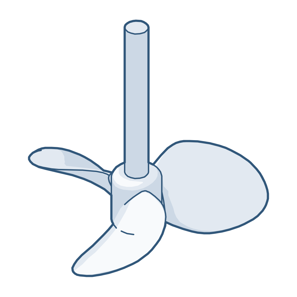
  • Marine propeller — 3 or 4 blades
  • Viscous-duty hydrofoil — wide blade, variable angle
Radial & high shear
  • Flat-blade turbine
  • Flat-blade disc turbine (Rushton type)
  • Concave-blade disc turbine
  • Curved-blade (backswept) turbine
  • Cowl-disc disperser (dissolver disc)
  • Gas-dispersion & hollow-shaft gas-induction impellers
Multi-stage & combined
  • Counter-flow multi-stage impeller — two stages, opposed blade angles
  • Hydrofoil + turbine combinations on one shaft
  • Foam breakers and surface impellers
  • Coil impellers with in-shaft heating or cooling
Close-clearance & viscous
  • Anchor and pipe anchor
  • Baby anchor / tickler
  • Gate and paddle
  • Helical ribbon — single or double
  • Helical screw
  • Wall scrapers
Special duty
  • Retreat-curve impeller
  • Large-diameter low-speed impeller
  • Side- and bottom-entry mixers
  • Special-purpose impellers designed around the duty

These are generic descriptions of the impeller families we design and build — including the counter-flow multi-stage, viscous-duty hydrofoil, helical-ribbon and curved-blade types often known by their makers' trade names. Tell us the duty and we will propose the design.

Impeller types at a glance

Some of the conventional impellers we manufacture, grouped by flow pattern. Each is sized for the duty and made in the alloy of the vessel.
Axial flow

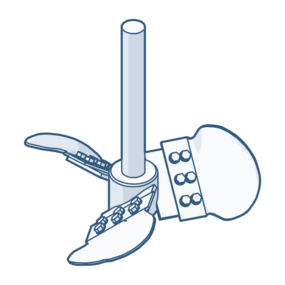
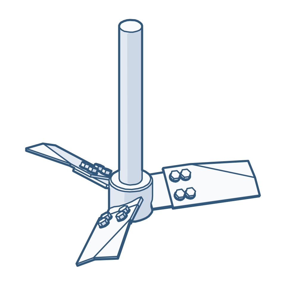
Line drawing of a three-blade hydrofoil impeller with rectangular bolted blades and bent ends
HydrofoilRectangular plate blades set at 30 degrees with bent ends. Low shear, high pumping at low power.
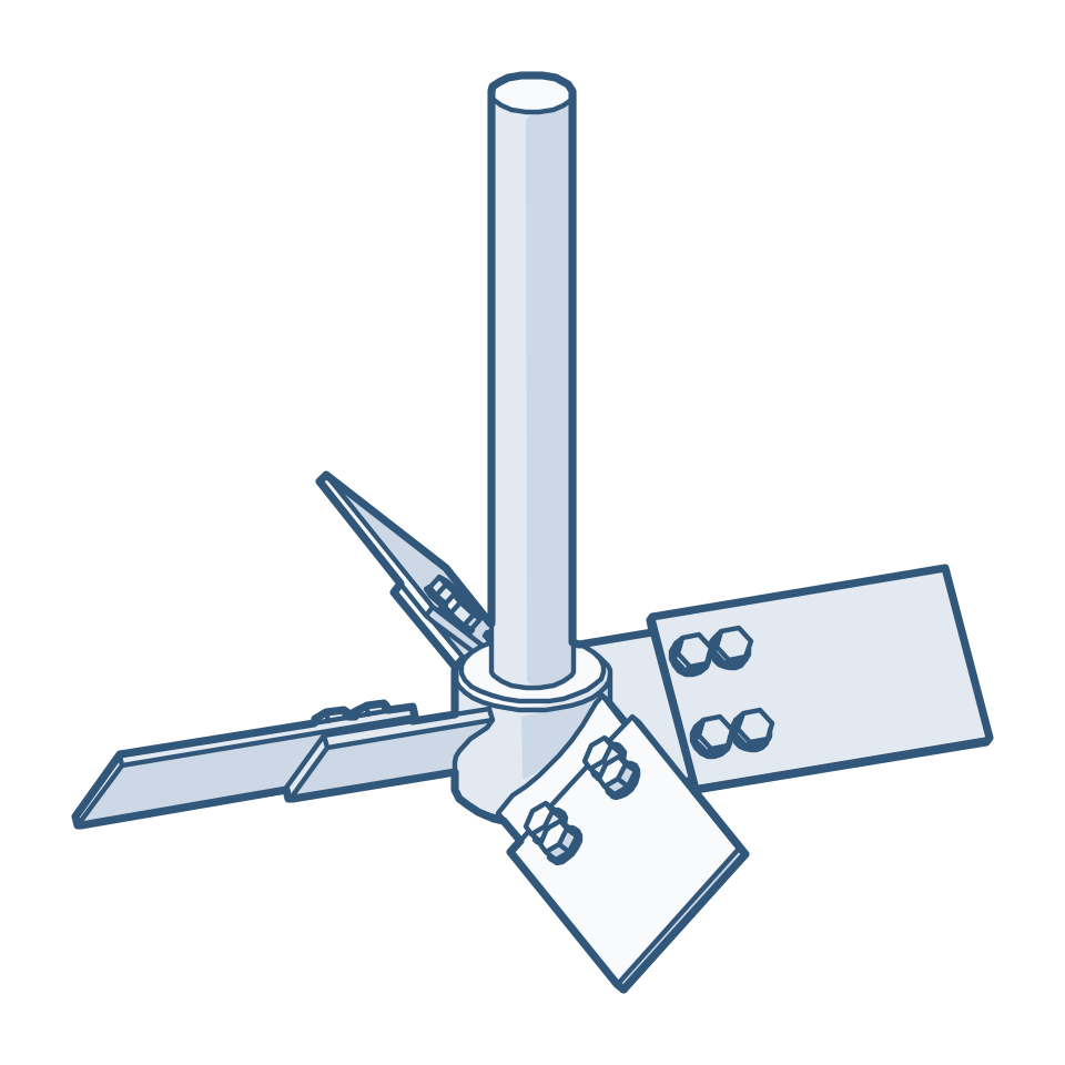
Line drawing of a four-blade pitched-blade turbine with blades at 45 degrees
Pitched-blade turbineAxial and radial mix for general-purpose reaction duties, 2 to 6 blades.
Line drawing of a three-blade marine propeller
Marine propellerStrong axial flow for blending low-viscosity liquids, 3 or 4 blades.
Line drawing of a wide-blade hydrofoil impeller
Viscous-duty hydrofoilWide blade that keeps pumping as viscosity rises.

Radial flow and gas

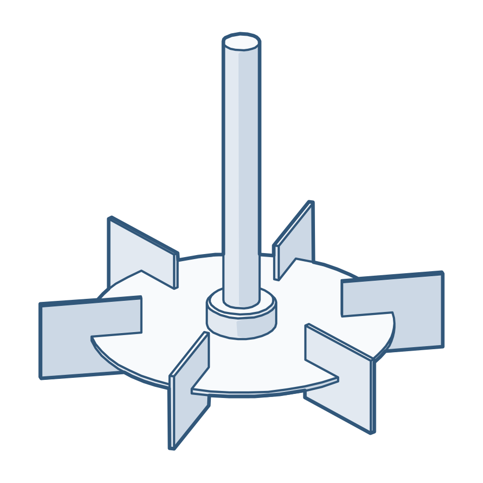
Line drawing of a six-blade flat-blade disc turbine
Flat-blade disc turbineRadial flow and high shear for gas and liquid-liquid dispersion.
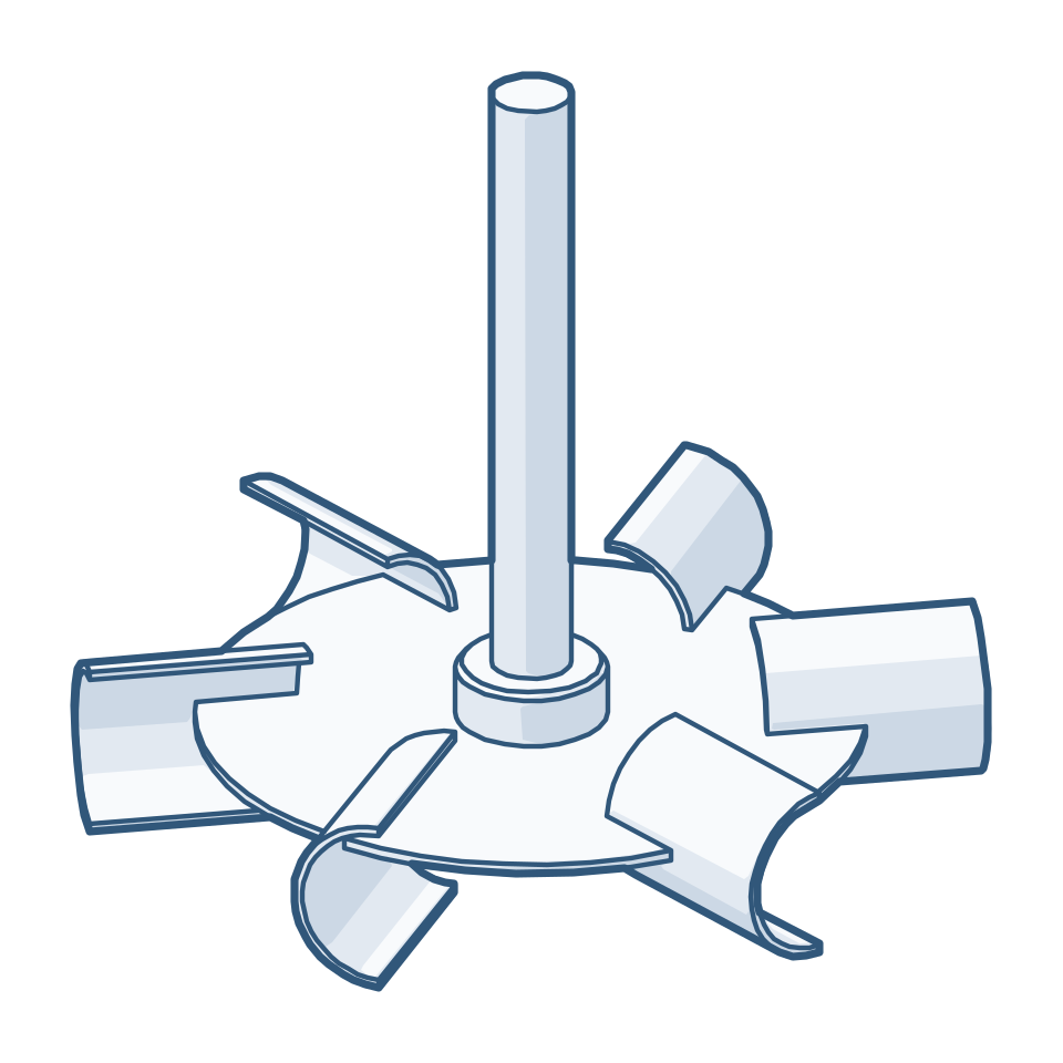
Line drawing of a disc turbine with six concave half-pipe blades
Concave-blade disc turbineGas dispersion at high gas rates with a steadier power draw.
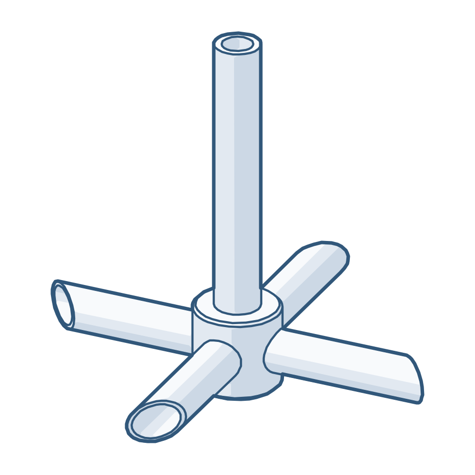
Line drawing of a hollow-shaft gas-induction impeller with four hollow pipe arms
Gas-induction impeller, pipe typeHollow shaft and hollow arms draw gas from the headspace back into the liquid.
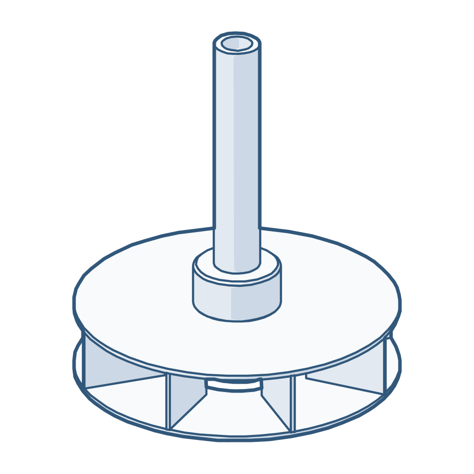
Line drawing of a hollow-shaft gas-induction impeller with a double-disc turbine
Gas-induction impeller, turbine typeHollow shaft feeding a double-disc turbine with radial vanes, for hydrogenators.

Counter-flow and high shear

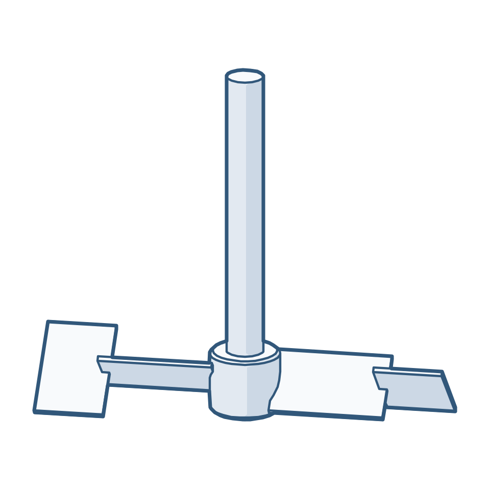
Line drawing of a counter-flow impeller with reverse-flow end plates welded to the main blades
Counter-flow impeller, plate endsReverse-flow end plates welded onto the main blades at the opposed angle. Used in stages on one shaft.
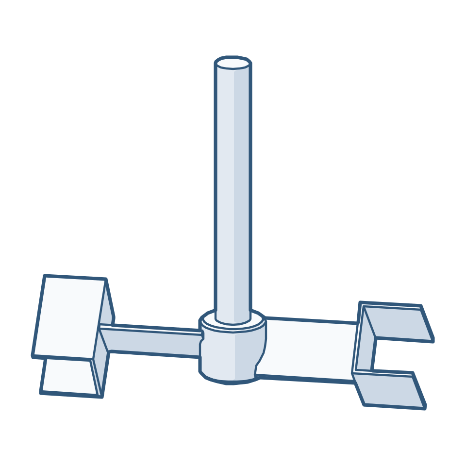
Line drawing of a counter-flow impeller with C-channel reverse-flow ends
Counter-flow impeller, channel endsThe same principle with a C-channel welded on each main blade end. Its two flanges are the reverse-flow blades.
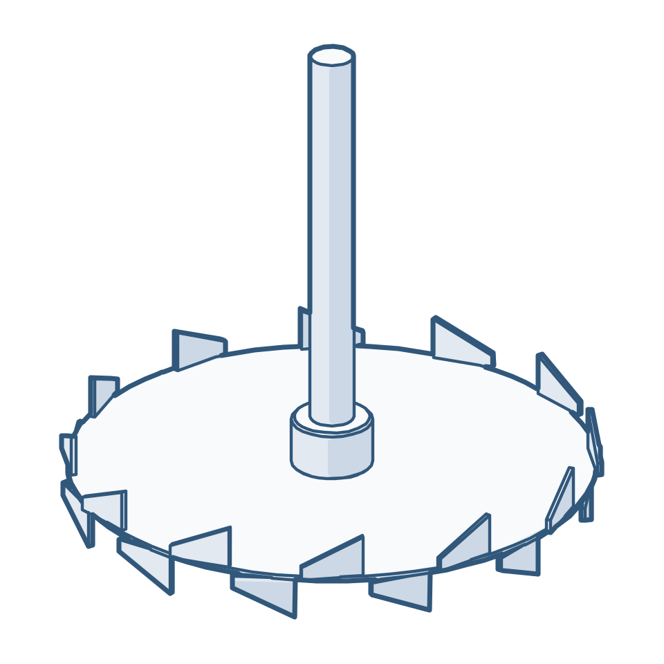
Line drawing of a saw-tooth cowl-disc disperser
Cowl-disc disperserHigh-speed dispersion of pigments, inks, paints and adhesives.

Close-clearance and special duty

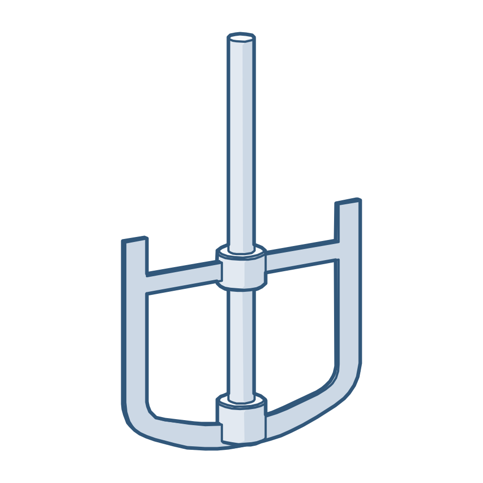
Line drawing of an anchor impeller
AnchorWall sweep for viscous products and better wall heat transfer.
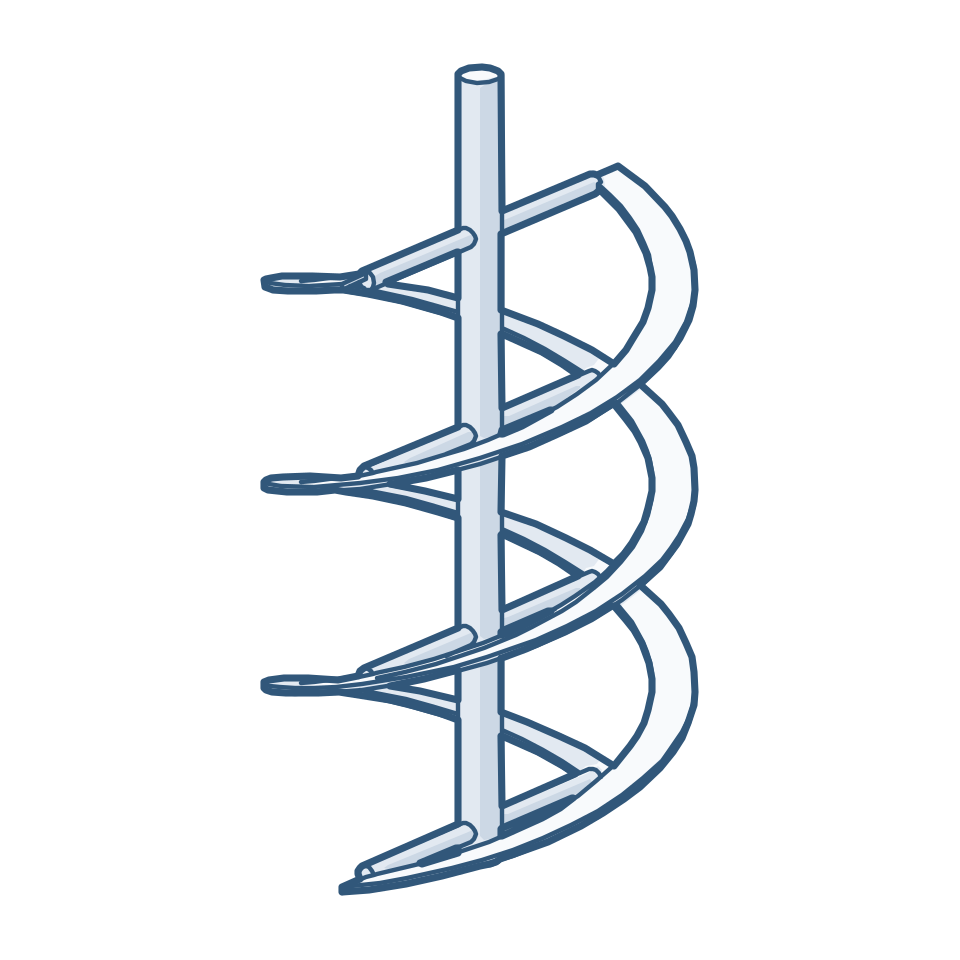
Line drawing of a double-flight helical ribbon impeller
Helical ribbonTop-to-bottom turnover in highly viscous products, single or double flight.
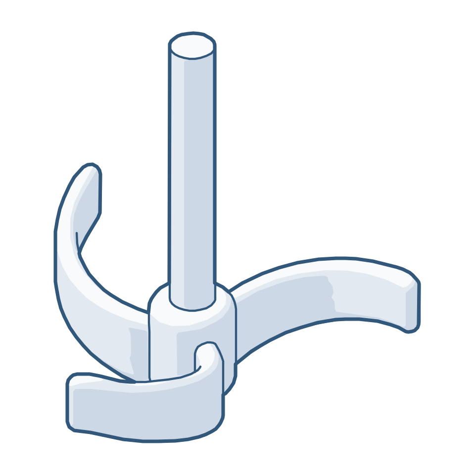
Line drawing of a three-blade retreat-curve impeller
Retreat-curve impellerThree swept blades for low-viscosity blending and heat transfer.

These are some of the conventional impellers we manufacture. We also design and manufacture other types to suit the process and the project requirement.

Illustrations of generic impeller types, not to scale.

Configurations we build

Entry & mounting
Top, side or bottom entry · centre-line or offset · baffled or unbaffled vessels
Flow pattern
Axial, radial, tangential and close-clearance designs · single or multi-stage shafts
Drives
FLP / non-FLP motors, flange- or foot-mounted · inline, parallel or right-angle gearboxes
Sealing
Single or double mechanical seal, stuffing box or sealless magnetic-drive coupling
Materials
SS 304 / 316L / 904L, duplex grades, Hastelloy C-276 and other alloys — solid, clad, mirror-polished or electropolished
Vertical agitator test bench in the Steelcon assembly bay
Trial-run before dispatch Static and dynamic balancing · air run (runout, vibration, noise, sweep, verticality) · water run at working pressure (rpm, amps, temperatures) · hydrostatic testing · alignment and seal checks — on our vertical trial bench, 12 m hook height

Every assembly is run on our in-house benches and the results — speeds, balance, alignment and test records — go into the documentation dossier with the equipment.

What to tell us about your mixing duty

A drawing or datasheet is ideal. If you are starting from the process, these points let our engineers propose an impeller and drive in the first reply.

The process Capacity, specific gravity and viscosity; what the agitator must achieve — blend, suspend, disperse gas or solids, transfer heat.
The vessel Inside diameter and TL–TL length, head types, baffles, design pressure and temperature, construction code and stamping.
The assembly Entry and mounting, number of stages, impeller type if known, rpm, motor (FLP / non-FLP) and gearbox preference.
Sealing & materials Seal type, wetted and non-wetted materials, surface finish — or simply the medium, and we will propose them.
Send your mixing datasheet

Related

Mixing & dispersion equipment Hydrogenators High & exotic alloys

No datasheet yet? Enter the design data you have, section by section, and we will work out the rest.

Technical enquiry form