
Skip to content

Hydrogenator masters.

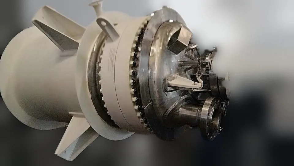
High-pressure hydrogenators, gas-induction reactors and autoclaves are among our most demanding — and most repeated — builds, for India's leading pharmaceutical, agrochemical and specialty-chemical producers.

Discuss your hydrogenation duty
20 m³
Limpeted hydrogenators
70 kg/cm²g
High-pressure hydrogenator
C-276
Explosion-bonded clad hydrogenator
−35 °C
to 280 °C design temperatures handled

Illustration, not to scale

Inside a hydrogenator

Built around gas, heat and pressure.

A gas-induction hydrogenator, part by part. Each numbered part is something we design, build and prove in our own works.

Scroll to open it up.

Drive and seal01 / 05

1Drive
FLP motor and gearbox, matched to the vessel, the seal and the site conditions.
2Shaft seal
Double mechanical seal or sealless magnetic drive.

Gas dispersion02 / 05

3Hollow shaft
Draws gas from the headspace back down into the liquid.
4Impeller assembly
On the vessel centre line, inside the coil: a gas-induction turbine above a gas-dispersion turbine, for high gas hold-up.

Heat transfer03 / 05

5Internal coil
Concentric with the vessel, around the impeller assembly; heat transfer inside the vessel.
6Limpet coil or jacket
On the shell; design temperatures from −35 °C to 280 °C.

Pressure boundary04 / 05

7Pressure shell
Full vacuum to 70 kg/cm²g, in SS 316L, 316Ti, 304L, 904L, CS and explosion-bonded Alloy C-276.
8Baffles
Baffled or unbaffled, to suit the flow pattern.

The whole assembly05 / 05

Eight parts, one works.

Designed, built and proved in our own works, and reviewed against your process before fabrication starts.
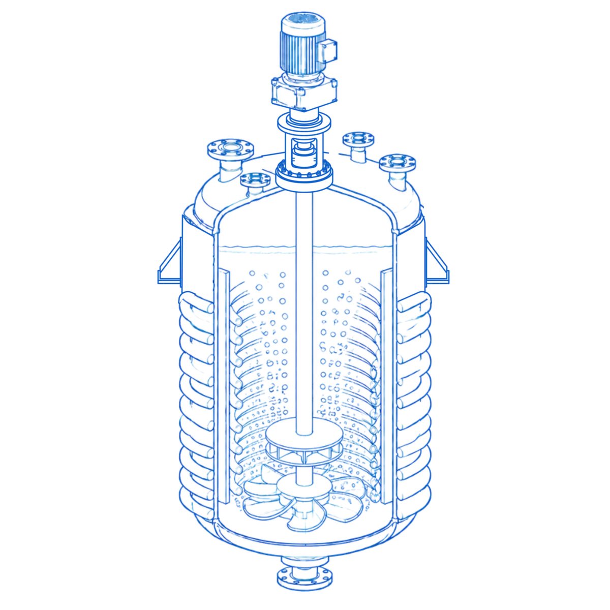
Cut-away illustration of a hydrogenator. Numbered parts: 1 drive, 2 shaft seal, 3 shaft, 4 impeller assembly on the centre line (a gas-induction turbine above a gas-dispersion turbine), 5 internal coil concentric with the vessel, 6 limpet coil on the shell, 7 pressure shell, 8 baffles. Bubbles show the dispersed gas rising through the liquid.
Illustration, not to scale
Inside a hydrogenator

Built around gas, heat and pressure.

A gas-induction hydrogenator in section. Each numbered part is something we design, build and prove in our own works.

  1. 1DriveFLP motor and gearbox, matched to the vessel, the seal and the site conditions.
  2. 2Shaft sealDouble mechanical seal or sealless magnetic drive.
  3. 3Hollow shaftDraws gas from the headspace back down into the liquid.
  4. 4Impeller assemblyOn the vessel centre line, inside the coil: a gas-induction turbine above a gas-dispersion turbine, for high gas hold-up.
  5. 5Internal coilConcentric with the vessel, around the impeller assembly; heat transfer inside the vessel.
  6. 6Limpet coil or jacketOn the shell; design temperatures from −35 °C to 280 °C.
  7. 7Pressure shellFull vacuum to 70 kg/cm²g, in SS 316L, 316Ti, 304L, 904L, CS and explosion-bonded Alloy C-276.
  8. 8BafflesBaffled or unbaffled, to suit the flow pattern.

Gas-induction impellers we build

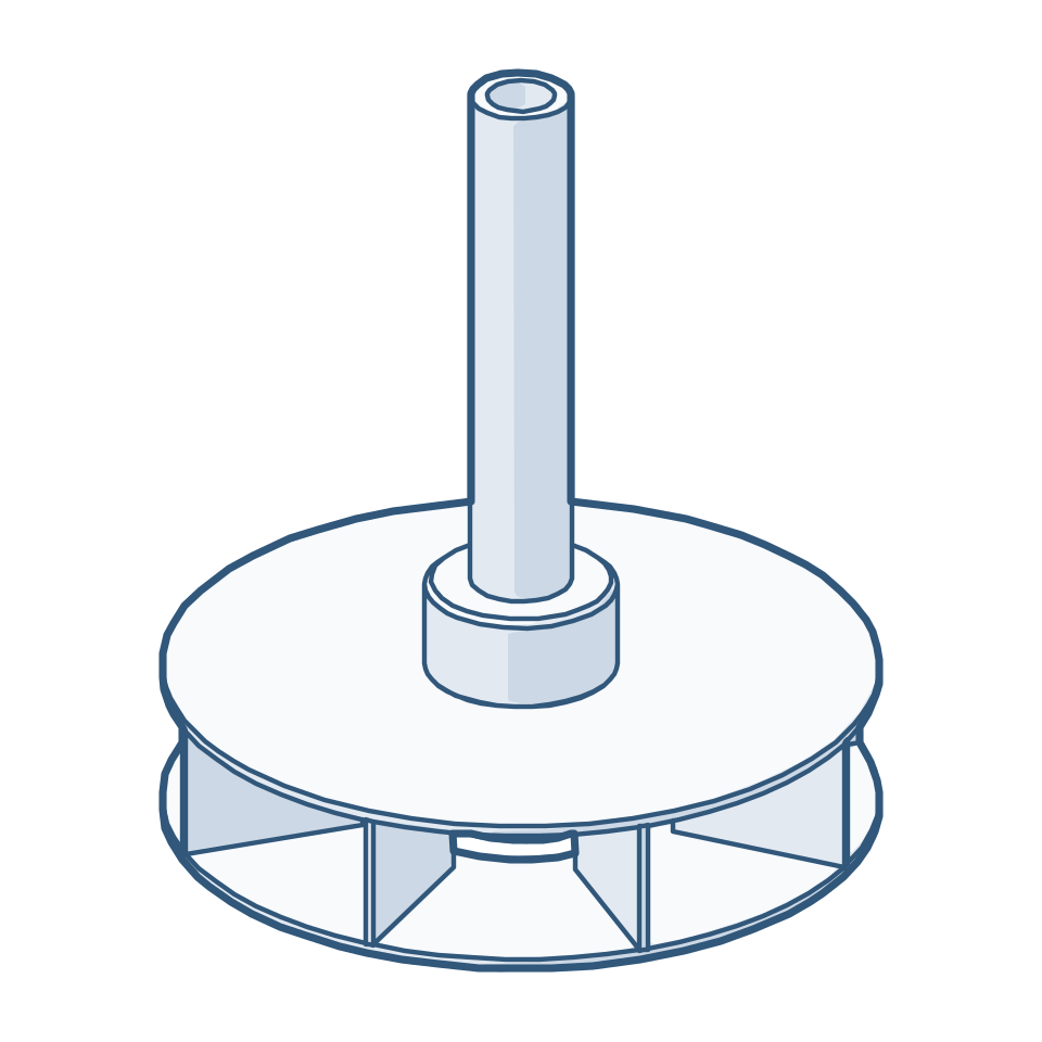
Both draw gas from the headspace through the hollow shaft back into the liquid. The type is chosen for the duty.
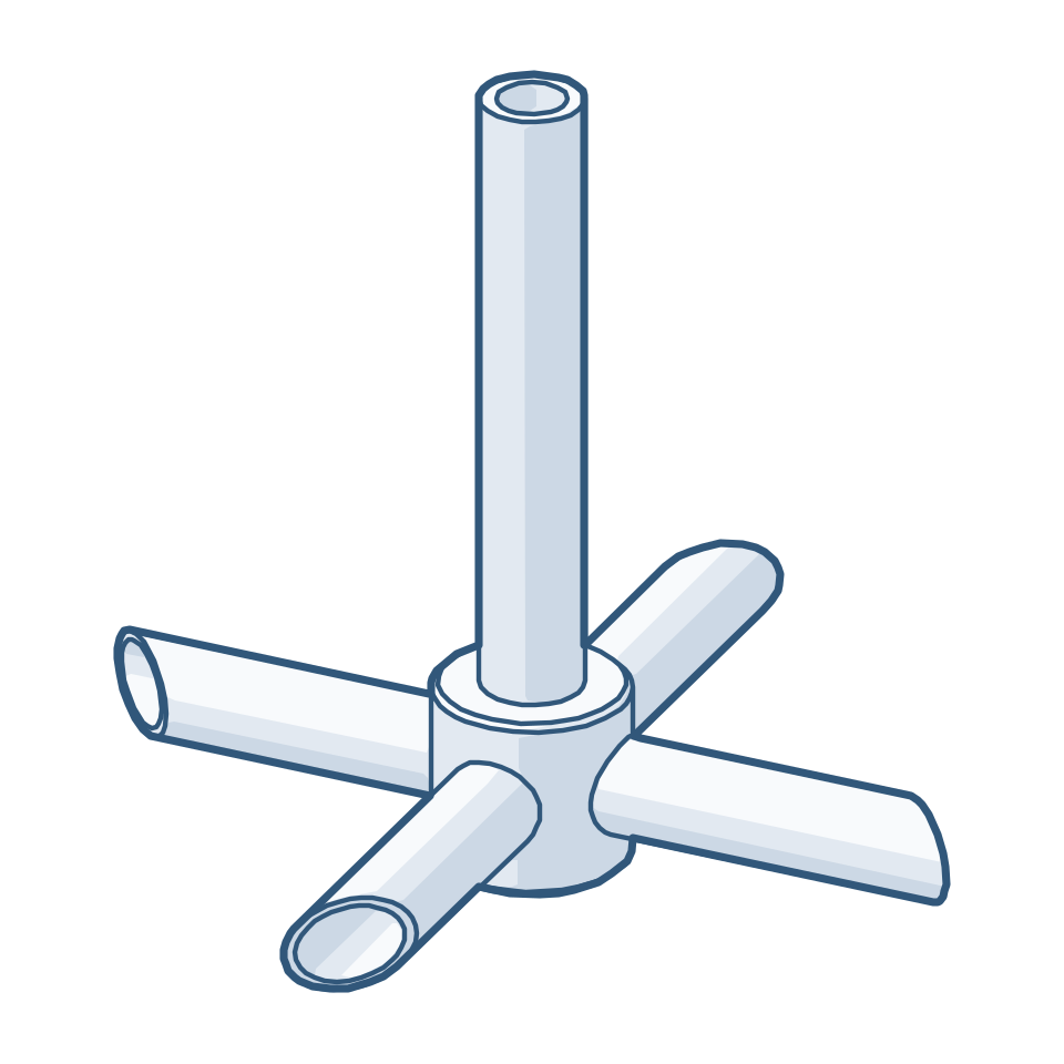
Line drawing of a hollow-shaft gas-induction impeller with four hollow pipe arms
Gas-induction impeller, pipe typeHollow shaft and hollow arms draw gas from the headspace back into the liquid.
Line drawing of a hollow-shaft gas-induction impeller with a double-disc turbine
Gas-induction impeller, turbine typeHollow shaft feeding a double-disc turbine with radial vanes, for hydrogenators.
All impeller types

Our record so far — and growing

Capacities
From pilot-scale 200 L units to 20 m³ production hydrogenators
Design pressures
Full vacuum to 70 kg/cm²g
Design temperatures
Cryogenic −35 °C to 280 °C
Materials
SS 316L, 316Ti, 304L, 904L, CS and Alloy C-276 explosion-bonded
Sealing
Double mechanical seal or sealless magnetic drive
Configurations
Limpet, jacketed and internal-coil; gas-induction; cGMP / GMP; ASME U autoclaves

Indicative of equipment already supplied, not a limit. Larger volumes, higher pressures and other configurations are engineered to suit your process.

Internal coil assembly inside a hydrogenator
Internal coil assembly
Gas-dispersion impeller
Super impeller for gas induction
Super impeller
Autoclave with drive assembly
Autoclave

No datasheet yet? Enter the design data you have, section by section, and we will work out the rest.

Technical enquiry form