



Agitator assemblies
Agitators designed for the duty: impeller selection, shaft and seal design, drive sizing, and a trial run on our vertical test bench before dispatch. Drives to 150 HP are in our references.
Agitator assemblies, impellers, mixers, blenders and sand mills — designed with the vessel and proven on our in-house trial bench before dispatch.
What we build under this heading, with the page and the detailed enquiry form for each type.
Agitators designed for the duty: impeller selection, shaft and seal design, drive sizing, and a trial run on our vertical test bench before dispatch. Drives to 150 HP are in our references.

Horizontal blenders, mixing vessels and high-speed dispersers for paints, resins, inks and speciality chemicals, built as complete machines with seal, drive and frame.
Illustration, not to scale
Anatomy of an assembly
A top-entry agitator on a jacketed, baffled vessel, part by part. Side- and bottom-entry, centre-line or offset, and multi-stage shafts follow the same logic.
Scroll to open it up.
Drive01 / 05
Mounting and seal02 / 05
Shaft and impellers03 / 05
Vessel and flow04 / 05
The whole assembly05 / 05
Agitator assemblies and impellers are built in the alloys our reactors are made of, and trial-run on our own benches before they leave Ankleshwar.
For engineers who check: open a panel for the detail behind each claim.
ASME BPVC Section VIII Div. 1 & 2 with U stamp and National Board registration, EN 13445, PD 5500, TEMA, API 650, IS 803, AD 2000-Merkblatt with HP0, PED 2014/68/EU (Annex I 3.1, Module A2 under CE 0045, Module G), ATEX 2014/34/EU and IBR 1950.
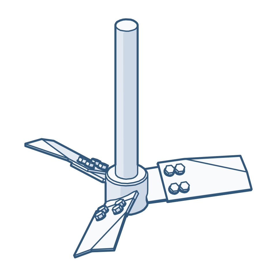
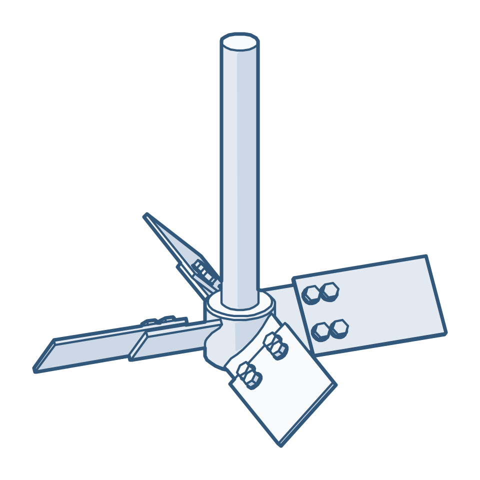
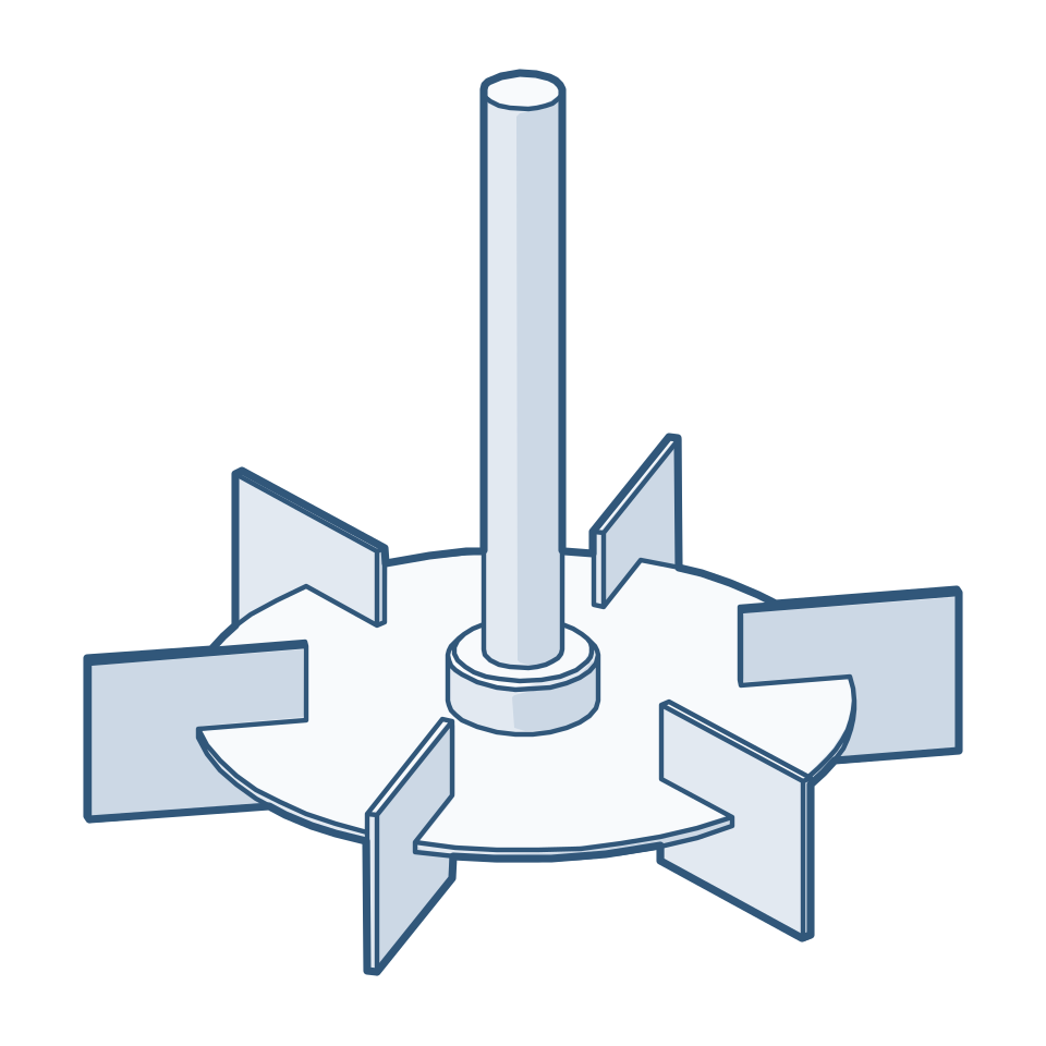
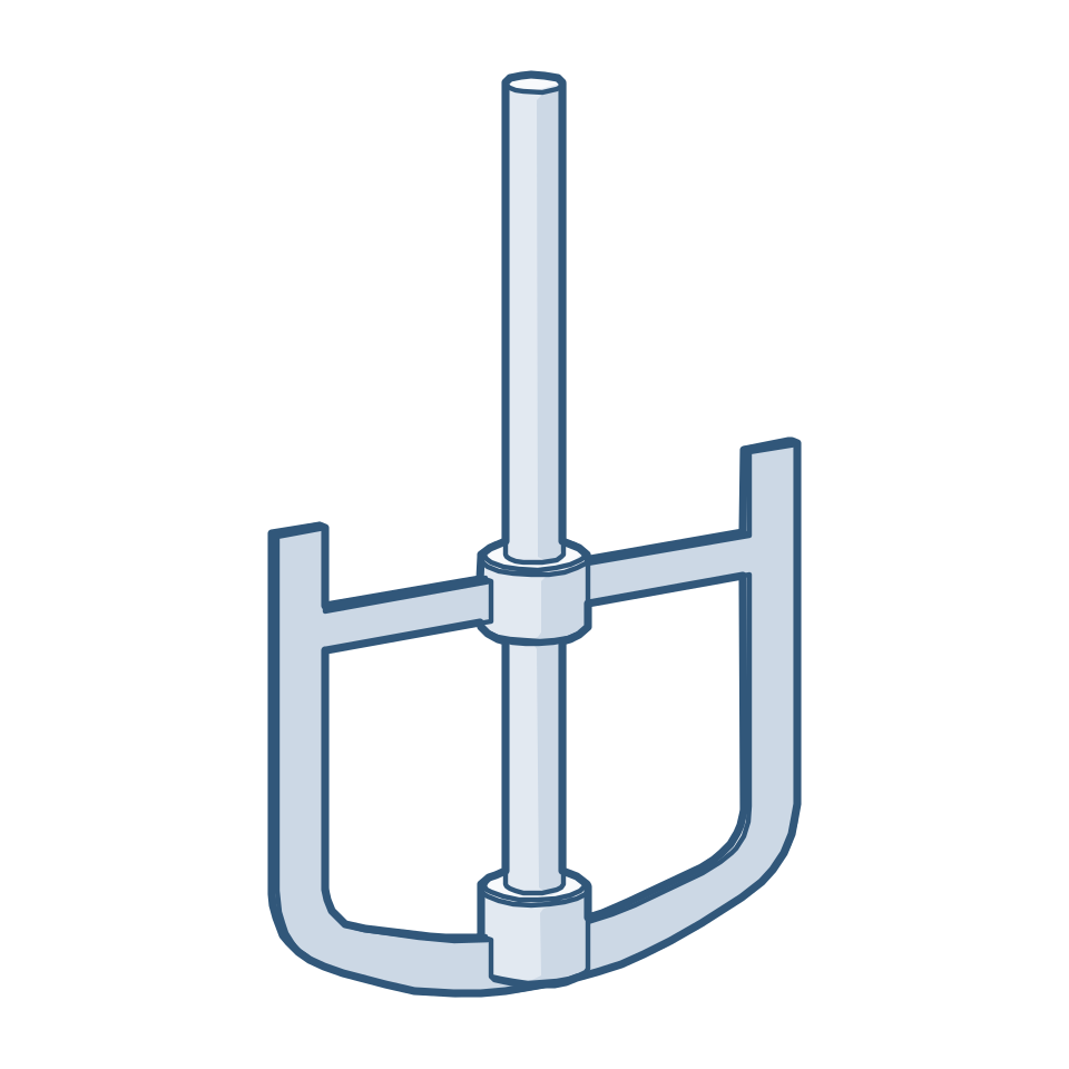
Impeller selection and staging (hydrofoil, PBT, Rushton, gas-induction, anchor, cowl-disc); shaft and seal design with double mechanical seals or magnetic drive; baffle and coil interaction reviewed; every assembly run on our trial bench.
Stainless steels including 304L, 316L, 316Ti and 904L; duplex, super-duplex and hyper-duplex; Hastelloy C-276, C-22 and C-2000; Inconel, Incoloy, Monel, Alloy 20, Sanicro 28 and nickel; carbon and low-alloy steels — in solid or explosion-bonded clad construction, and many more related grades.
Approved ITP and QAP; stage inspection by third-party agencies; RT, UT, PT, MT and VT by in-house ASME NDE Level II personnel; PMI on every finished item; hydrostatic or pneumatic testing; a complete dossier with material traceability.
Detailed references are available on request.
See all project examples →Send the datasheet or drawing — the RFQ form arrives with this solution already selected.
Read about our agitator assembly & impeller design speciality →Some of the conventional impellers we manufacture. We also design and manufacture other types to suit the process and the project requirement.
No datasheet yet? Enter the design data you have, section by section, and we will work out the rest.
Technical enquiry form