

Skip to content
Equipment · Regenerators & tubular catalytic reactors

Regenerators and tubular catalytic reactors. Built for continuous catalytic processes.

Regenerators for continuous processes, and vertical multi-tubular reactors in which the reaction runs inside catalyst-filled tubes while a heat-transfer medium round them holds the temperature. Our references include a 3.5 m, 8,800-tube formaldehyde reactor.

Regenerators

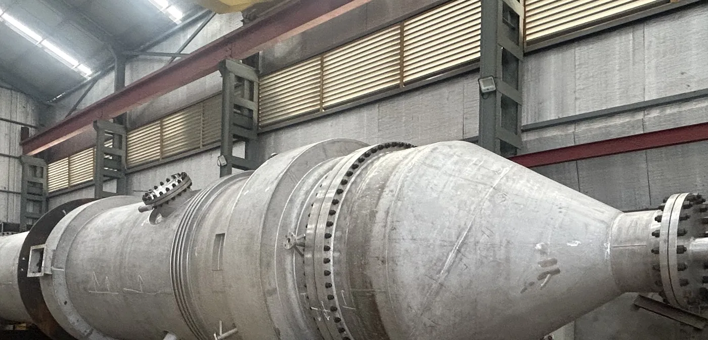
A regenerator in our works.

Regenerators for continuous processes are built to the customer's process design. The photographs show one in our fabrication bay.
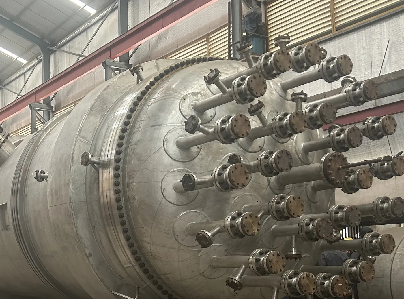
Regenerator in the fabrication bay: top head with its nozzles, girth flange and shell expansion joint
Regenerator: top head with its nozzles, girth flange and shell expansion joint.
Regenerator in the fabrication bay: conical section, girth flange and shell-side nozzle
Regenerator: conical section, girth flange and shell-side nozzle.
  • Top head. Carries a large number of nozzles.
  • Girth flanges. Join the sections of the vessel.
  • Conical section and shell expansion joint. As on the regenerator in the photographs.
Tubular catalytic reactors

A heat exchanger that is also a reactor.

Between two tube-sheets stand the catalyst tubes. Process gas enters the top channel, passes down through the catalyst and leaves at the bottom channel. On the shell side a heat-transfer medium circulates across the tubes to carry the heat of reaction away.
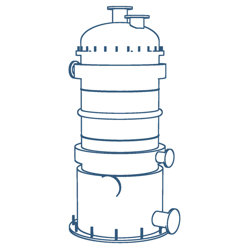
Outline drawing of a vertical tubular catalytic reactor
Vertical tubular catalytic reactor. Illustration, not to scale.
  • Catalyst tubes. On a close pitch between two fixed tube-sheets.
  • Top and bottom channels. Dished or conical heads with the process nozzles and manways for catalyst handling.
  • Shell. With ring channels that feed and collect the heat-transfer medium evenly round the shell.
  • Baffles. Guide the heat-transfer medium across the bundle.
  • Expansion joint. Takes up the difference in expansion between the shell and the tubes.
  • Skirt. Carries the reactor and gives access to the bottom channel.

Illustration, not to scale

Inside a tubular catalytic reactor

Thousands of tubes, one temperature.

A vertical multi-tubular reactor: the reaction runs inside catalyst-filled tubes while a heat-transfer medium around them carries the heat away.

Scroll to open it up.

Shell and channels01 / 05

1Shell
References include a reactor of 3.5 m diameter.
2Top channel
Process gas enters above the top tube-sheet.
3Bottom channel
Product gas leaves below the bottom tube-sheet.
4Skirt
Skirt support with access to the bottom channel.

Tube bundle02 / 05

5Catalyst tubes
Our references include a reactor with 8,800 tubes.
6Tube-sheets
Tube-to-tube-sheet joints welded and expanded with in-house expanders.
7Baffles
Guide the heat-transfer medium across the bundle.

Two sides03 / 05

Reaction inside, heat transfer outside.

The process gas passes down through the catalyst in the tubes. The heat-transfer medium circulates round the tubes and holds the temperature of the reaction.

  • Process gas, through the tubes
  • Heat-transfer medium, round the tubes

Shell-side details04 / 05

8Ring channels
Feed and collect the heat-transfer medium evenly round the shell.
9Expansion joint
Takes up the difference in expansion between the shell and the tubes.

The whole reactor05 / 05

Multi-tubular reactors from our own works.

References include a 3.5 m, 8,800-tube formaldehyde reactor. Tubular reactors are designed to the code you specify, with stage inspection and a complete dossier.

What matters in the build

Where the work is.

Tube-sheets

Large, thick tube-sheets drilled for thousands of tubes; flatness and hole pattern checked before tubing.

Tube-to-tube-sheet joints

Welded and expanded with in-house tube expanders, then tested.

Shell-side flow

Ring channels, baffles and nozzles laid out so that every tube sees the same heat transfer.

Access for catalyst

Channels and manways arranged for loading, unloading and inspection.

From our record

References, not limits.

3.5 mShell diameter of a tubular reactor
8,800Tubes in one reactor
FormaldehydeProcess of that reference
For engineers who check

Codes, materials and inspection.

  • Codes and standards. ASME Section VIII Div. 1 and 2 with U stamp and National Board registration, EN 13445, TEMA, PD 5500, AD 2000-Merkblatt with HP0, PED 2014/68/EU and IBR 1950.
  • Materials of construction. Stainless steels including 304L, 316L, 316Ti and 904L; duplex and super-duplex; Hastelloy C-276, C-22 and C-2000; Inconel, Incoloy, Monel, Alloy 20 and nickel; carbon and low-alloy steels, in solid or explosion-bonded clad construction.
  • Inspection, testing and documents. Approved ITP and QAP, stage inspection by third-party agencies, NDE by in-house ASME Level II personnel, PMI on every finished item, hydrostatic or pneumatic testing and a complete dossier with material traceability.

Have a regenerator or tubular reactor to quote?